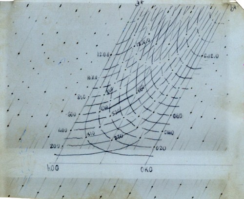
This
deformation is such that any reciprocal line, passing through
the
centre of the reciprocal lattice, appears in the diagram as a line of
spots lying on a straight line with slope 2. Furthermore, the
angle between two reciprocal lines that intersect each other in the
reciprocal lattice is shown in
the diagram as the distance between two parallel lines, as it is
shown in the figure below:
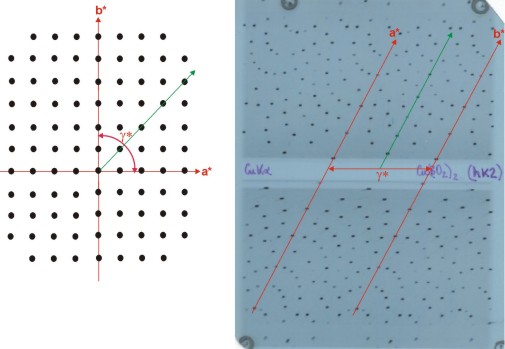
Geometric
distortion of a reciprocal plane (figure on the left) when
collected on a Weissenberg diagram (figure on the right).
Template
drawn on a real Weissenberg diagram for the interpretation of the
diffraction spots. These templates were used for the measurements of
diffraction intensities in a manual photometer, so one could identify
all spots with their Miller indices.

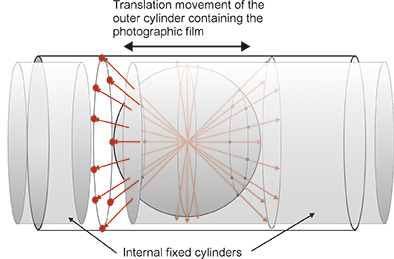 A
genuine Weissenberg
diagram
consists of isolating a reciprocal plane (therefore perpendicular to
one direct axis of the crystal, which acts as the rotation axis), and
collecting on a cylindrical photographic plate all the diffracted beams
coming from the reciprocal points on that plane. The filtering of the
diffracted beams from the selected reciprocal plane is carried out by
including two internal metal cylinders that leave a slit allowing the
diffracted beams from that plane to reach the photographic film.
A
genuine Weissenberg
diagram
consists of isolating a reciprocal plane (therefore perpendicular to
one direct axis of the crystal, which acts as the rotation axis), and
collecting on a cylindrical photographic plate all the diffracted beams
coming from the reciprocal points on that plane. The filtering of the
diffracted beams from the selected reciprocal plane is carried out by
including two internal metal cylinders that leave a slit allowing the
diffracted beams from that plane to reach the photographic film.